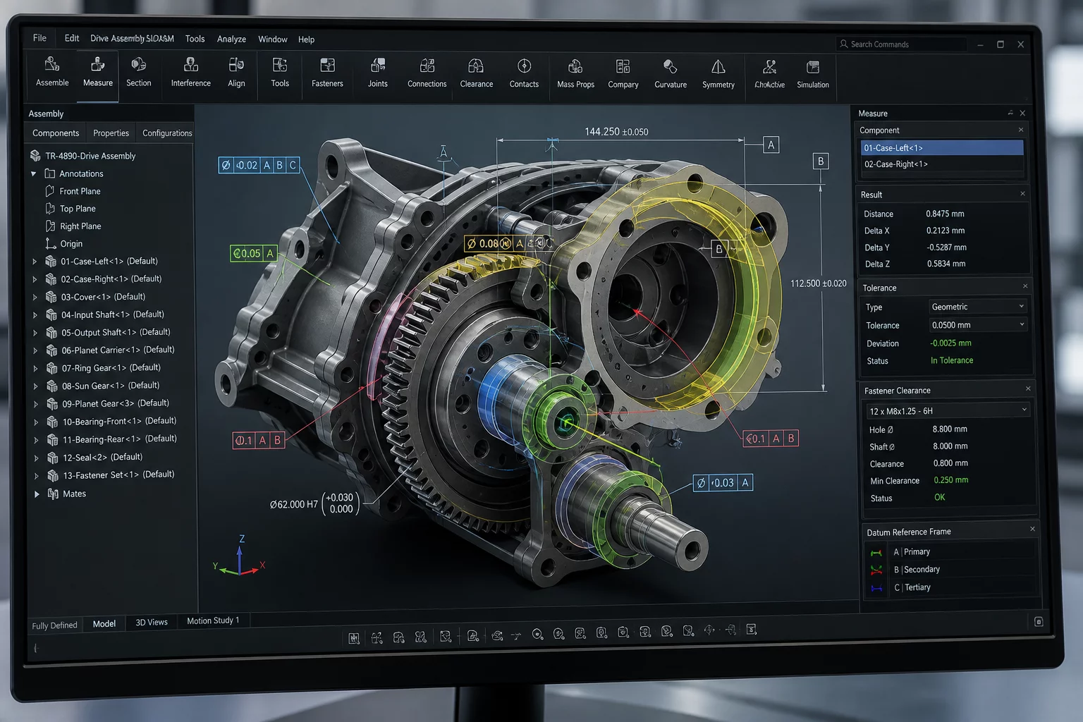
Explore how clearance, mating geometry, access, alignment, assembly sequence, and neighboring components shape interface decisions.
A mechanical-interface atlas about why two parts interact the way they do. Not CAD tutorials. Not a tolerance calculator. We break down the design reasoning behind interfaces: mating surfaces, clearance, locating features, fastener access, assembly direction, neighboring geometry, and service access.
"What has to remain true for this interface to work?"
Select a parameter to examine the primary constraint rule:
Primary planar faces establish position and eliminate degrees of freedom before fasteners clamp.

Founder, InterfaceReason Atlas
Inside modern solid modeling software, components never collide unexpectedly, fasteners tighten without socket clearance, and surfaces mate with zero tolerance stack-up. The screen creates a deceptive illusion of certainty.
Over two decades of designing robotic structures and industrial machinery, I watched brilliant engineers lose months to simple interface oversights: a blocked wrench path, an ambiguous datum surface, or an assembly sequence that required three hands inside a closed enclosure.
We created InterfaceReason Atlas to shift the paradigm from passive component modeling to active assembly reasoning. Every lesson and breakdown here revolves around our singular engineering inquiry:
"What has to remain true for this mechanical interface to work reliably across its entire lifecycle?"
Every interface decision traces back to one of these six fundamental reasoning domains. Master them to predict failures before they reach the assembly line.
What actually controls fit. The primary planar contacts and datum schemes that establish position before anything else is considered.
Not just gap size, but why it's needed. Understanding the functional purpose behind every tolerance zone and interference margin.
Can it be assembled and serviced. Verifying tool envelopes, hand clearance, and maintenance pathways before locking the design.
What else depends on geometry. Tracing how a single datum or surface change cascades through every connected sub-assembly.
In what order parts must connect. Defining non-reversible assembly paths and verifying that each step is physically achievable.
What changes after one revision. Predicting how a single geometry update propagates through drawings, fixtures, and downstream assemblies.
InterfaceReason Atlas decomposes mechanical validation into explicit milestone gates. Review the exact analytical artifacts, CAD checks, and physical acceptance deliverables at each control phase.
Establishes deterministic 3-2-1 locating schemes and verifies that cosmetic surfaces are never accidentally utilized as primary functional datums.
Worst-case statistical tolerance loops across all neighboring geometries, thermal expansion ranges, and structural deflection conditions.
Audits driver insertion envelopes, torque wrench clearances, socket wall thicknesses, and human hand clearance during single-axis fastener install.
Validates unambiguous top-down or unidirectional assembly pathways and guarantees wear components are serviceable without unbolting parent frames.
Explore rigorous training programs and real-world failure post-mortems focused on mating surfaces, stack-ups, and assembly geometry.
 Case StudyCAD vs Real
How an aesthetic skin line was accidentally promoted to a primary datum, shifting manufacturing variance into critical alignments.
 Case StudyCAD vs Real
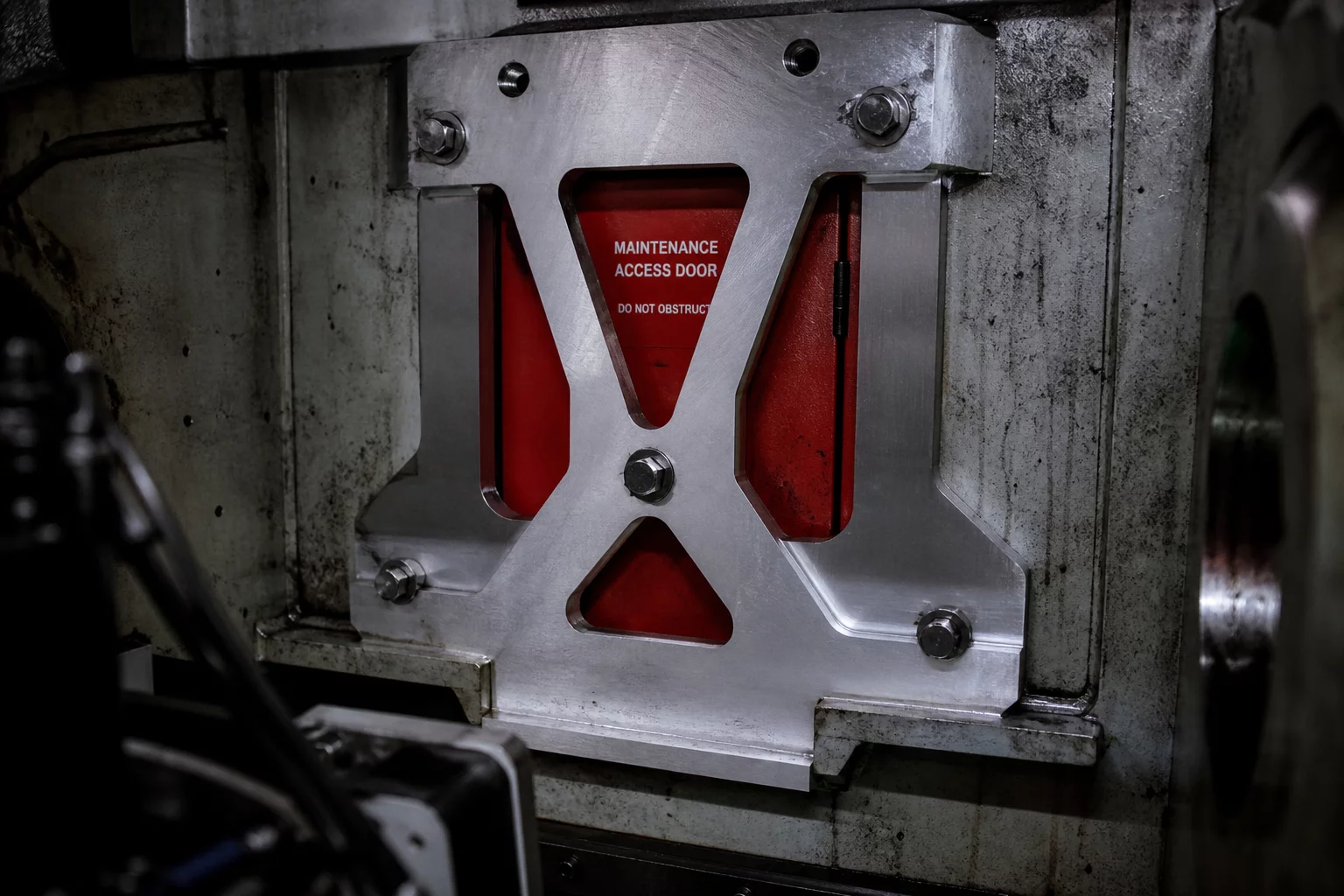
A structural revision bracket obstructed the technician's tool envelope, turning a 10-minute service task into a full teardown.
 Case StudyCAD vs Real
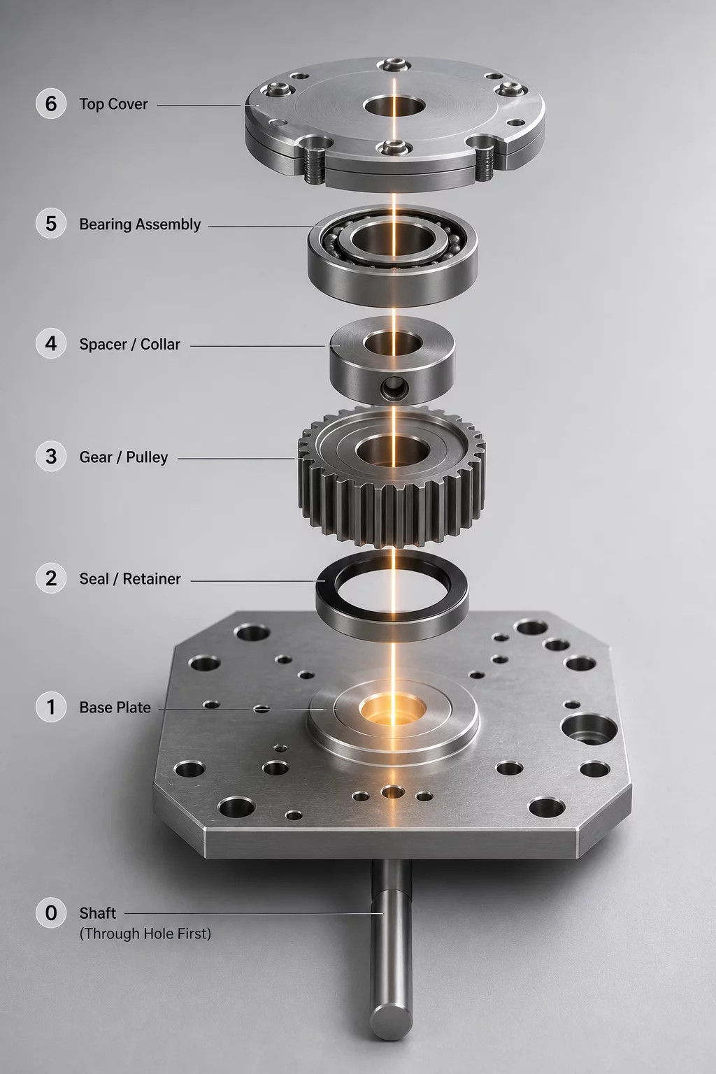
Analyzing how a single unthreaded dowel location constrained subassembly order and forced non-reversible manufacturing operations.
 Case StudyCAD vs Real
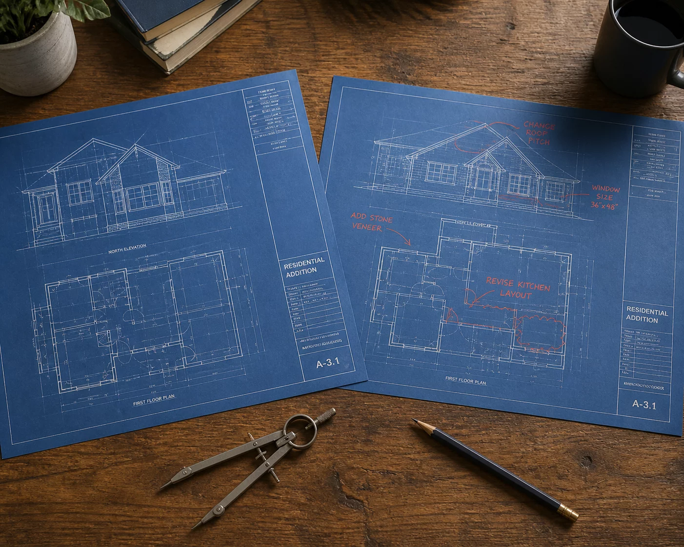
When a mating geometry revision was never reflected in the drawing callout, inspection passed parts that failed on the assembly line.
 Case StudyCAD vs Real
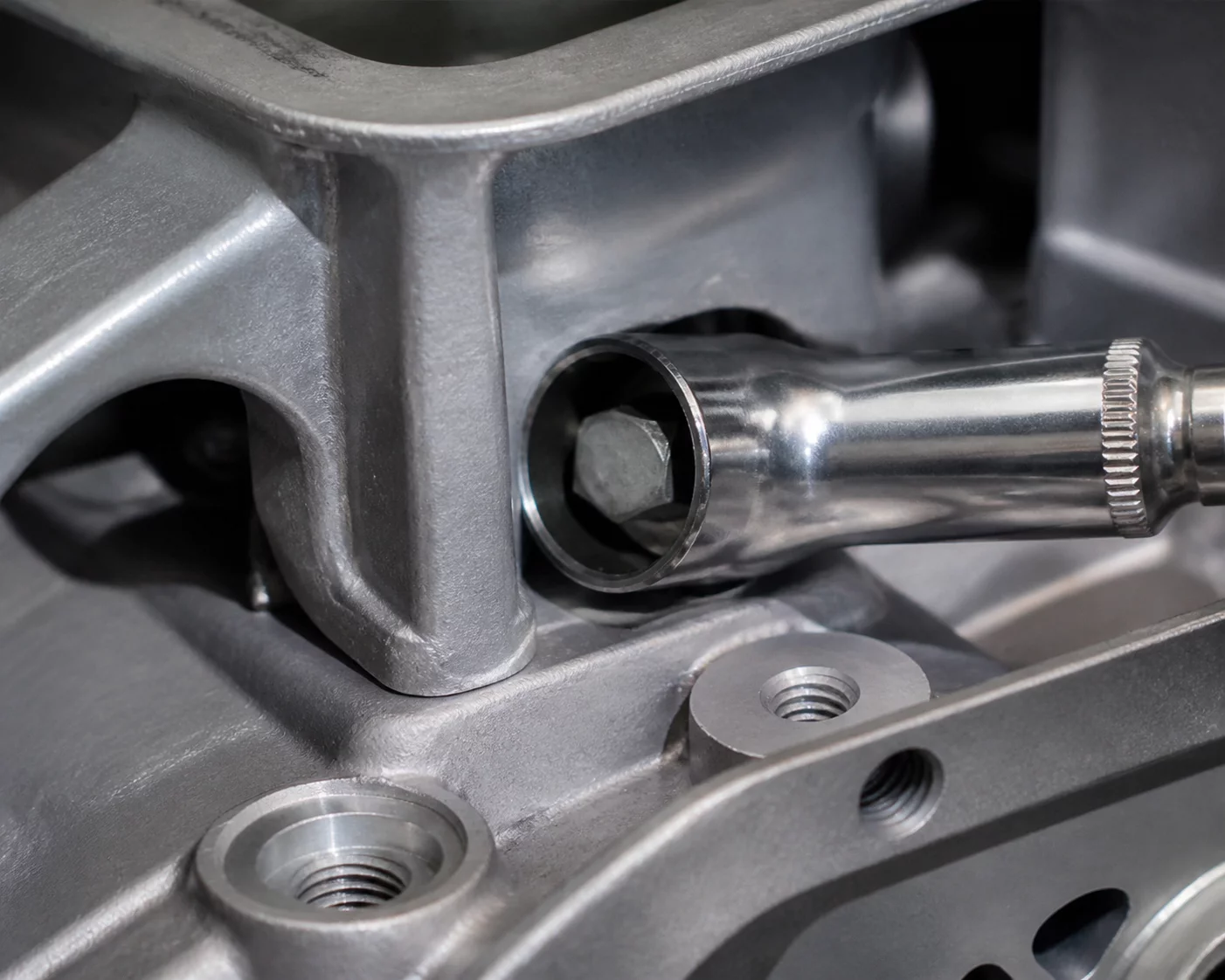
An in-depth post-mortem on how a structural rib blocked socket wrench rotation on the line.
 Case StudyCAD vs Real
Why increasing gap tolerances to solve binding caused severe mechanical vibration.
 Case StudyCAD vs Real
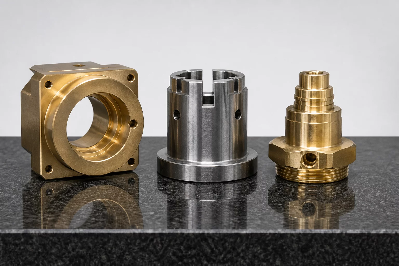
Examining unexpected over-constraint when three distinct sub-components share a single plane.
 Case StudyCAD vs Real
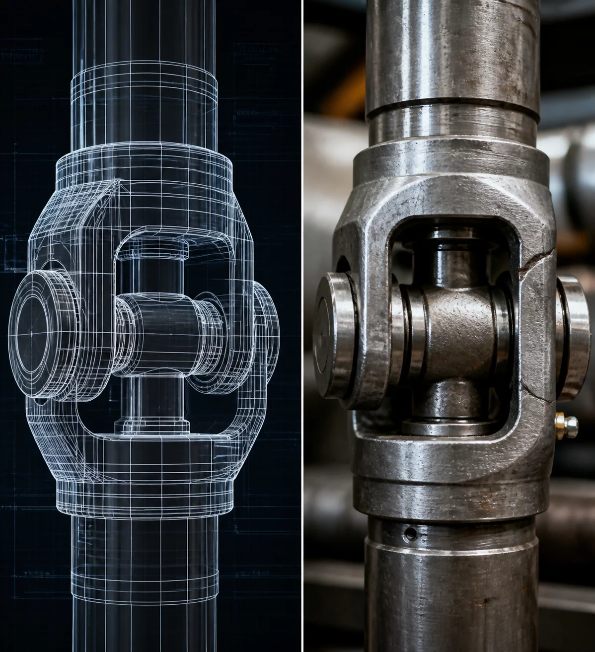
Addressing nominal CAD vs true physical assembly friction and coating thickness build-up.
Dive deeper into our complete Mechanism Breakdown library or explore the dedicated curriculum.
Build CAD models that withstand physical assembly. Explore how to integrate mating surfaces, fastener tool clearances, and rigid locating datums inside Autodesk Fusion 360 environments.
Standardized spatial sequencing rules and single-axis insertion checks to detect fastener tool lockouts early in the design cycle.