Root Interface Condition Analysis
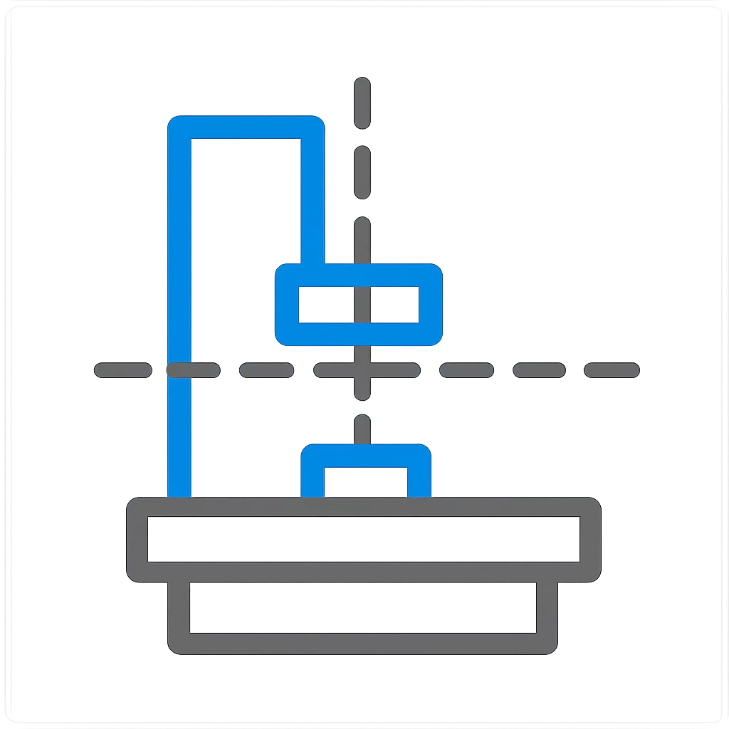
Enlarging clearance holes often seems like the quickest remedy when components jam during factory line assembly. In this dual-bracket mechanism, operators encountered binding when threading M6 fasteners through the guide arm into tapped base bosses. The engineering response increased through-hole clearances from standard 6.6 mm to an oversized 7.4 mm. Assembly time dropped, but operational test benches soon revealed rapid positional error accumulation. Without close-tolerance hole engagement or dedicated locating pins, the joint relied purely on fastener friction to resist alternating shear vectors.
Dual close-fit clearance bores center the mounting arm with less than 0.08 mm cumulative lateral play, allowing bolt pre-load to hold permanent geometric alignment throughout machine service life.
Enlarged 7.4 mm through-holes allowed the bracket to settle unpredictably off-axis before torque application, creating 0.8 mm end-effector play under cyclic reversing loads.
Dimensional & Tolerance Interplay
Fasteners are designed for clamping, not location. When a clearance hole expands beyond the nominal ISO medium fit standard, the mating part loses its predictable datum reference. In this mechanism, dynamic torque pulses exceeded the static friction coefficient between the anodized aluminum interfaces. The arm shifted inside the widened clearance envelope, degrading positioning accuracy by a factor of ten. The true remedy required separating the clamping task from locating duties by adding a round datum dowel and diamond pin pairing.