Root Interface Condition Analysis
Mating logic forms the structural backbone of every repeatable mechanical joint. In parametric 3D CAD modeling environments, engineers frequently apply mating constraints—such as planar mates, concentric axes, and tangencies—without fully considering physical assembly physics. A correct mating hierarchy establishes primary planar contact first to eliminate three degrees of freedom (one translation and two rotations), followed by secondary alignment features that suppress translational movement, and finally tertiary rotational locking. Ignoring this fundamental 3-2-1 constraint framework leads directly to over-constrained joints, physical binding during workshop assembly, and severe tolerance stack-up errors.
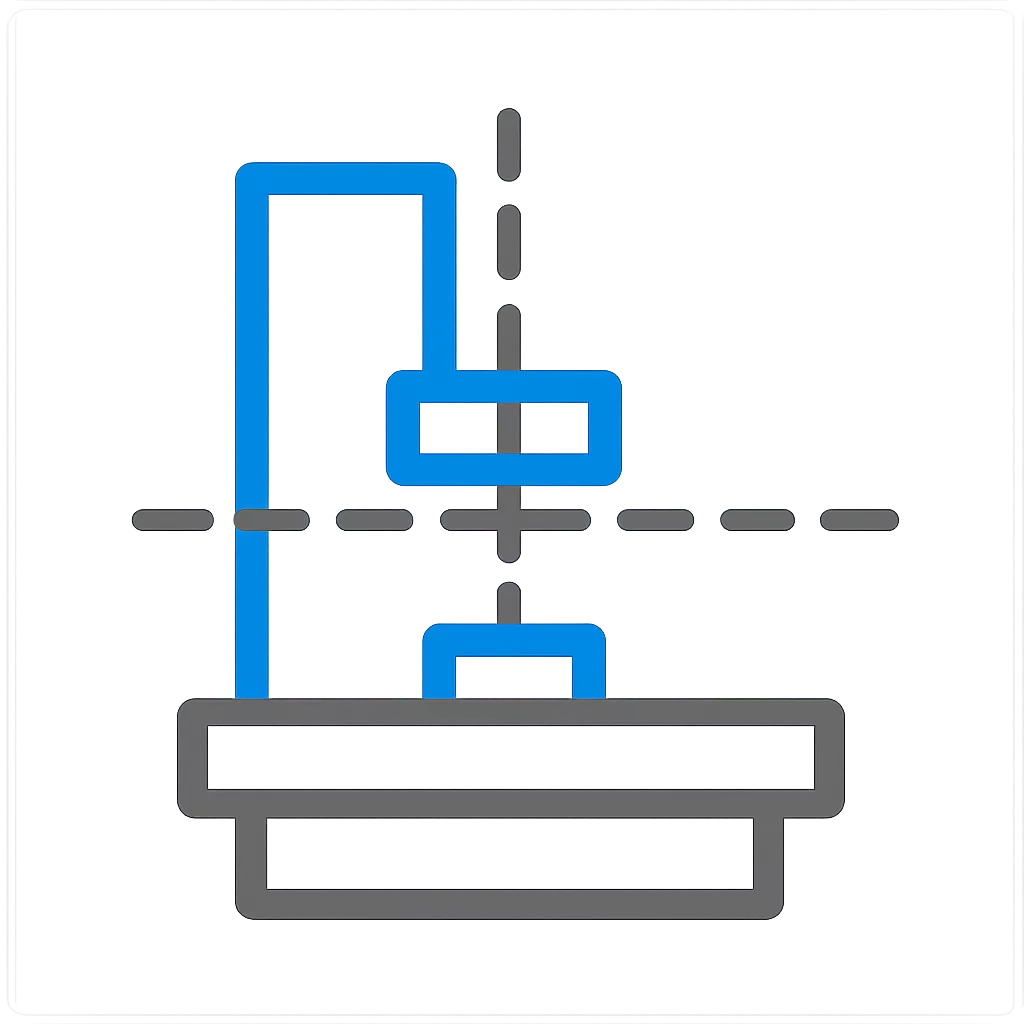
Clean planar seating across the primary datum plane A with dual cylindrical locating dowels arresting secondary and tertiary axes cleanly without interference.
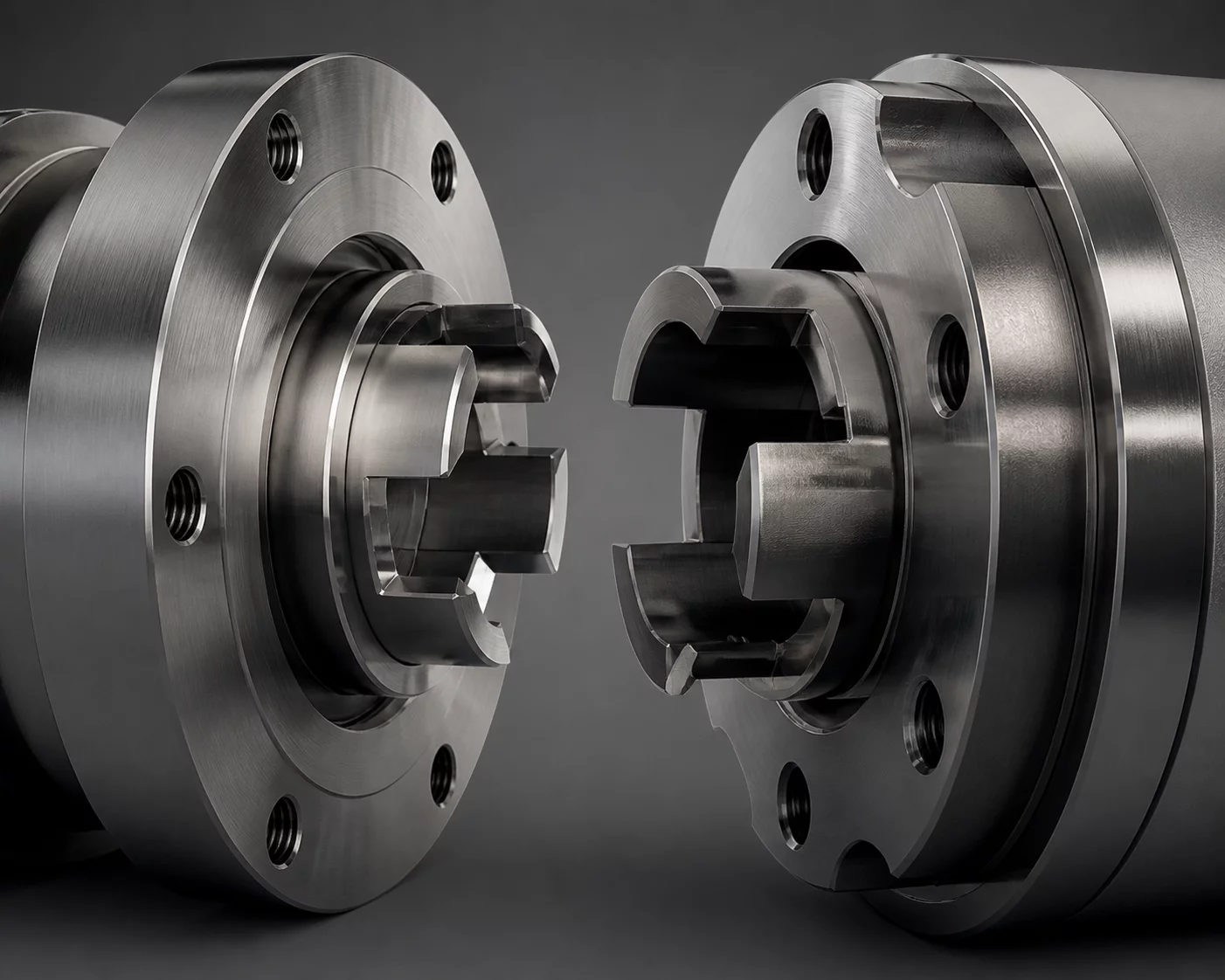
Over-constraining planar faces with redundant concentric fasteners causes thermal and manufacturing binding across multiple mounting bosses.
Dimensional & Tolerance Interplay
Dimensional allocation requires precise balance between primary contact pads and secondary locating features. When multiple concentric fasteners attempt to serve as both clamping mechanisms and primary locating datums, minute hole-pattern center variations induce extreme shear stresses on the assembly bolts. Proper kinematic design decouples locating functions from fastening forces, utilizing dedicated stepped locating pins alongside oversized clearance thru-holes for clamping hardware.