Interface Study 2026-08-16 Lead: Emma Watson

Design Dependencies and Geometry

Every mechanical part exists inside a network of geometric parent-child constraints. Establishing clean reference chains prevents circular dependencies, datum migration errors, and costly tooling modifications on the factory floor.

Prime Mechanical Inquiry

“What geometric, fastener, or datum condition must remain true for this joint to assemble without conflict?”

Interface Parameters

V-2026.8
Datum Type:
Hierarchical 3-2-1 Datum Chain
Tool Clearance:
28.5 mm Radial Envelope
Assembly Vector:
Uniaxial Z+ with Secondary Keying
Interface Status:
Fully Constrained / Verified
Jump to Full Breakdown
Mechanical Interface Breakdown Diagram
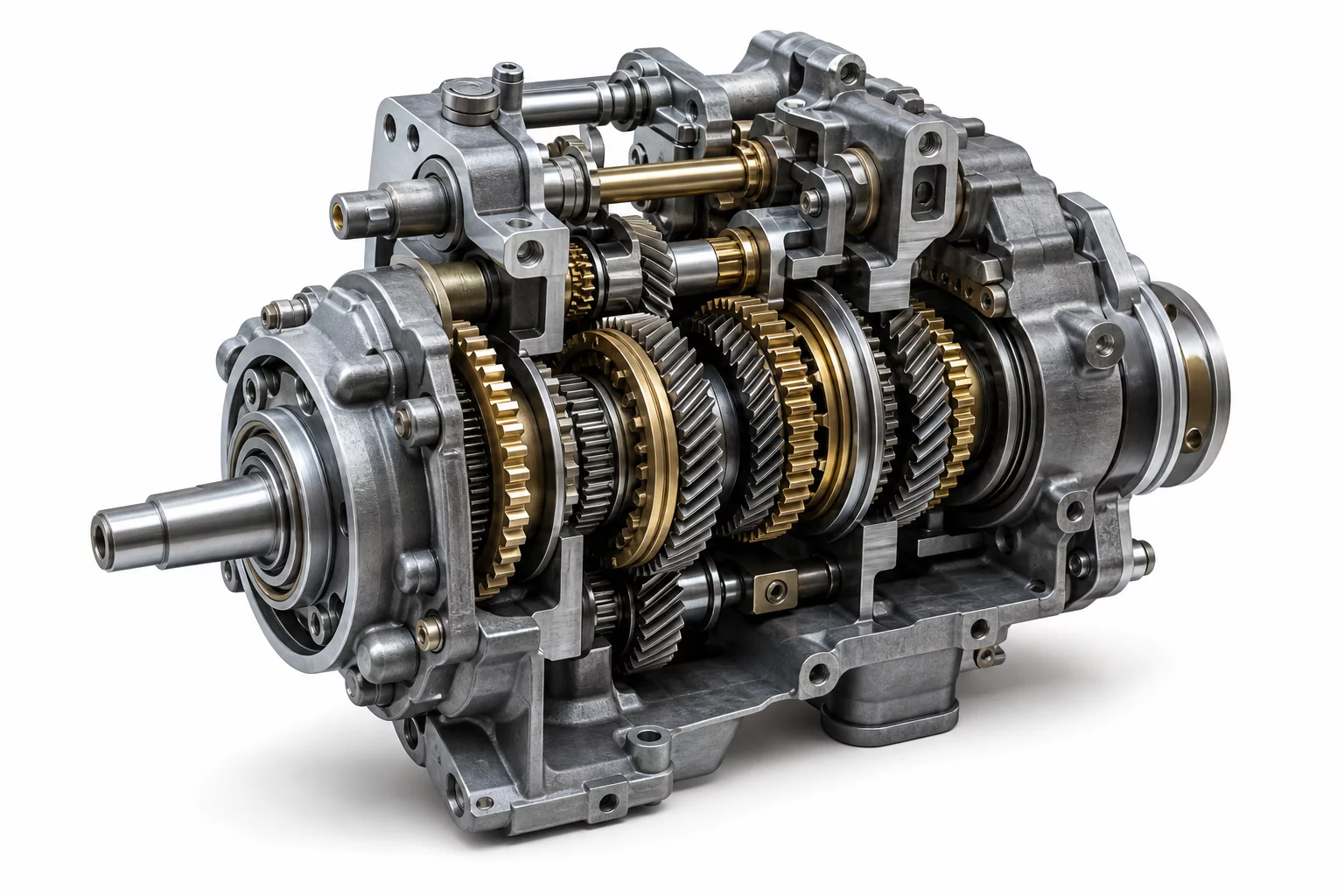
Primary Interface Section CAD View
Cross-section alignment model Interface Reason Repository #DEP-8492

Root Interface Condition Analysis

Geometric dependencies form the underlying skeleton of any mechanical subsystem. When a component references a secondary mating feature that itself lacks strict positional locking against the global base plate, errors cascade exponentially. Designers must isolate functional degrees of freedom before locking fastener locations. In this assembly structure, the primary planar datum absorbs pitch and roll, while dedicated dowel pins dictate position and eliminate rotational drift without overloading adjacent threads.

Intended Nominal Pathway

Direct linear alignment from the chassis master datum directly to the gear shaft carrier plate, allowing tolerance stack calculations to remain deterministic and strictly isolated within two direct manufacturing steps.

Actual Assembly Conflict

Secondary bracket mounting holes referenced a cosmetic sheet-metal flange, leading to cumulative angular deflection of 1.4° and binding the drive gears under nominal tightening torque.

Dimensional & Tolerance Interplay

True geometric dimensioning and tolerancing (GD&T) requires that each tolerance frame ties back to reproducible datum surfaces rather than floating edges. When calculating 1D and 3D stack-ups, cross-part dependencies inflate variations. Shifting the tertiary datum to an internal machined shoulder confines axial runout to ±0.03 mm, completely neutralizing the lateral backlash issues experienced during initial prototype trials.

Technical Verification Modules

Select a perspective below to inspect the interface solution details.

Datum & Locating Surface Controls

The structural baseline is set by an unbroken ground face that arrests three spatial degrees of freedom. A precision round dowel controls translational coordinates X and Y, whereas an offset diamond pin locks rotation while forgiving thermal expansion along the longitudinal axis.

  • Primary locating constraint: Plane A (Base Mounting Face)
  • Secondary pin locator: Feature B (Diamond Dowel Pin Ø6.00 mm)
  • Rotational orientation lock: Slot C (Machined Keyway Guide)

Frequently Examined Interface Issues