Interface Study 2026-08-18 Lead: Robert Davis

Assembly Sequence Planning

Systematic analysis of structural assembly order, fastener tooling clearance trajectories, and mechanical datum precedence in multi-part enclosures.

Prime Mechanical Inquiry

“What geometric, fastener, or datum condition must remain true for this joint to assemble without conflict?”

Interface Parameters

V-2026.8
Datum Type:
Hierarchical Kinematic Reference
Tool Clearance:
68.0 mm Radial Envelope
Assembly Vector:
Z+ Axial with Y- Tilt Insertion
Interface Status:
Verified Sequence Path
Jump to Full Breakdown
Mechanical Interface Breakdown Diagram
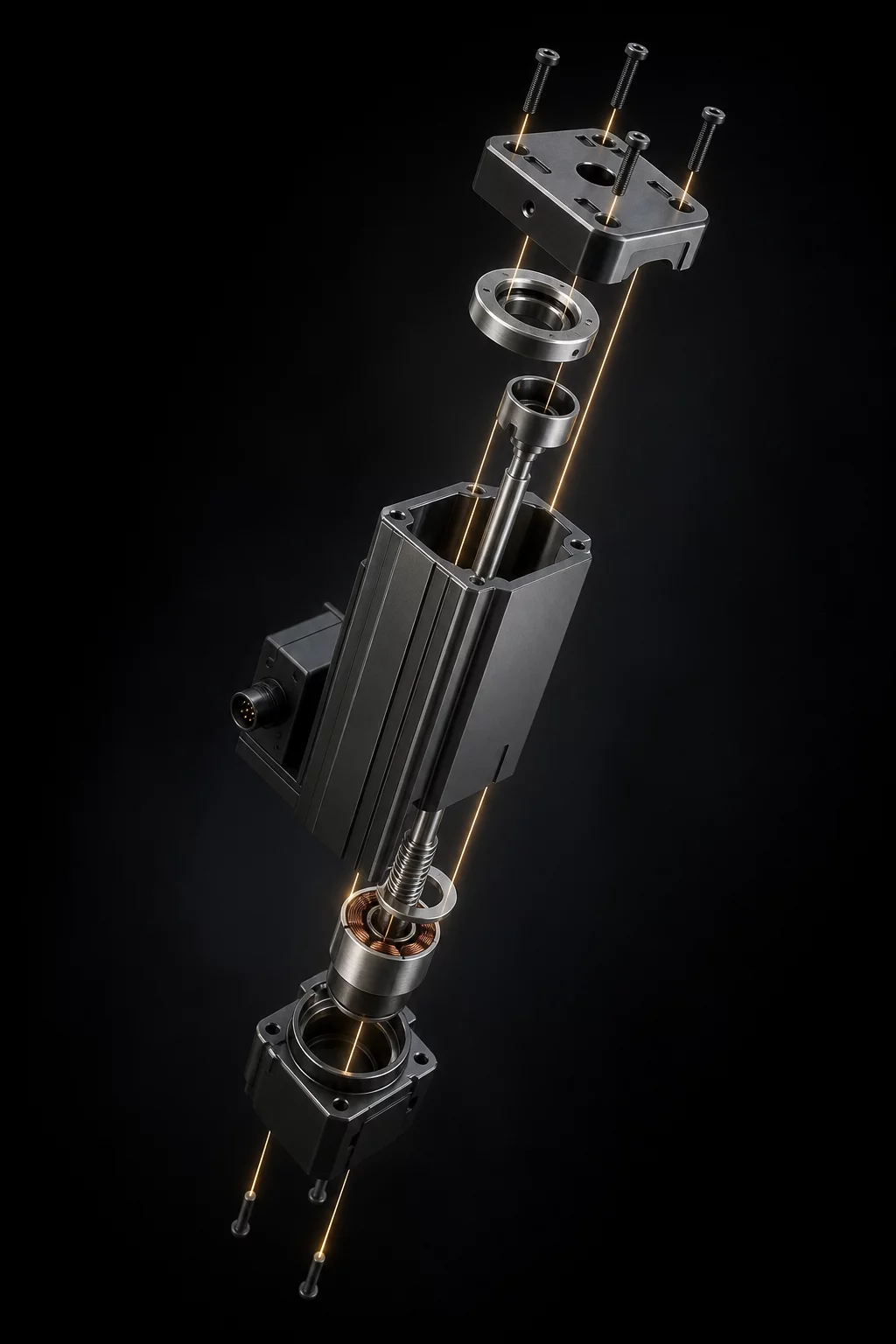
Primary Interface Section CAD View
Cross-section alignment model Interface Reason Repository #ASP-409

Root Interface Condition Analysis

Assembly sequence planning establishes the precise order in which discrete components integrate into a unified mechanism. When complex mechanical assemblies are built solely within digital CAD space, designers frequently overlook how physical hands and driver tools access hidden fasteners once structural covers drop into place. This interface breakdown dissects how nested brackets create spatial locks that prevent subsequent hardware insertion unless the assembly order obeys rigid geometric dependencies.

Intended Nominal Pathway

Base chassis receives the central actuator carrier first, followed by internal cable guide retainers, and concludes with perimeter structural stiffeners fastened from accessible exterior angles.

Actual Assembly Conflict

Installing outer structural brackets early completely obstructs line-of-sight and clearance drivers for inner M4 socket head screws, causing assembly deadlock on the production line.

Dimensional & Tolerance Interplay

Dimensional variations directly cascade through stacked tolerances when locating features control downstream components. In this assembly structure, the primary indexing boss aligns the main housing, while secondary dowels locate the gear carrier. If the assembly sequence forces the gear carrier into position before securing the base datums, cumulative clearance float shifts the drive axis by up to 0.42 mm, inducing severe gear mesh binding and fastener galling.

Technical Verification Modules

Select a perspective below to inspect the interface solution details.

Datum & Locating Surface Controls

The primary datum plane controls three degrees of freedom (Z-translation, X-rotation, Y-rotation) through a planar milled pad. Secondary and tertiary datums utilize a diamond-round pin configuration to position parts repeatably without inducing over-constraint during rapid manual assembly.

  • Primary locating constraint: Plane Surface A-1 (Main Base Pad)
  • Secondary pin locator: Feature Round Dowel Pin DP-04
  • Rotational orientation lock: Slot Diamond Slot SL-02

Frequently Examined Interface Issues