Root Interface Condition Analysis
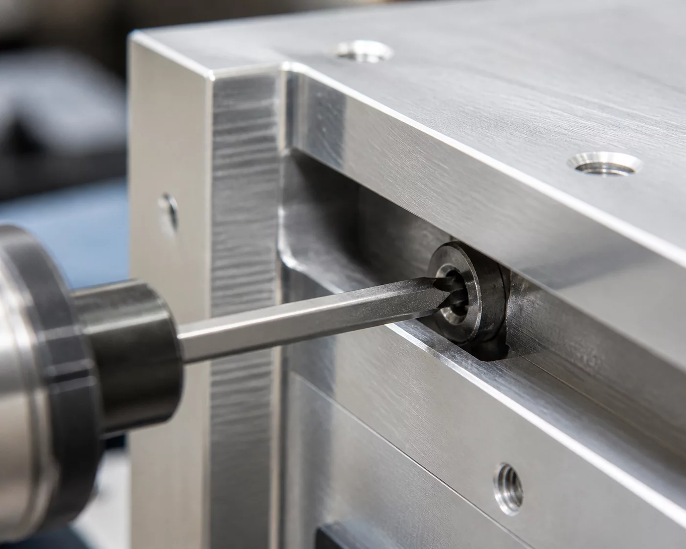
A bolt that fits in a digital 3D model often fails in physical reality when the tool required to torque it cannot fit within the surrounding housing walls. In complex enclosures, engineers routinely place fasteners adjacent to structural ribs or deep inside pocket geometries without modeling the driver bit, socket outer diameter, or manual finger clearance needed for initial thread engagement. Proper fastener access strategy demands treating the tightening tool and insertion trajectory as physical CAD bodies that consume space throughout the entire assembly cycle.
Direct axial insertion along the fastener centerline with uninterrupted 360-degree tool rotation and straight-line socket clearance.
Overhanging bracket flanges and neighboring rib gussets collide with the driver chuck, forcing severe angled bit engagement or complete assembly blockage.
Dimensional & Tolerance Interplay
Tool clearance envelopes depend directly on fastener head geometry, drive style, and specified torque values. Low-profile button-head hex drives require smaller radial clearance than standard hex flanged bolts, yet they demand precise axial alignment to prevent cam-out during torquing. When designing deep cavity access, engineers must account for socket wall thickness (often +3 to +6 mm beyond fastener nominal head diameter), wobble extension deflection angles (up to 15 degrees max without torque distortion), and physical line-of-sight during blind manual threading.