Interface Study 2026-07-15 Lead: Alan Smith

The Fastener Fit but the Tool Could Not Reach It

A solid 3D CAD model confirmed full volumetric clearance for the ISO 4762 cap screw inside the cavity, yet the shop floor could not tighten it. The missing parameter was not the static boundary of the hardware, but the dynamic swept volume required by the hex driver bit and manual torque tool.

Prime Mechanical Inquiry

“What geometric, fastener, or datum condition must remain true for this joint to assemble without conflict?”

Interface Parameters

V-2026.8
Datum Type:
Co-planar Flange Face
Tool Clearance:
Ø18.5mm / 65mm Depth
Assembly Vector:
+Z Normal Vector (Obstructed)
Interface Status:
Clearance Envelope Flaw
Jump to Full Breakdown
Mechanical Interface Breakdown Diagram
Primary Interface Section CAD View
Cross-section alignment model Interface Reason Repository #MB-409

Root Interface Condition Analysis

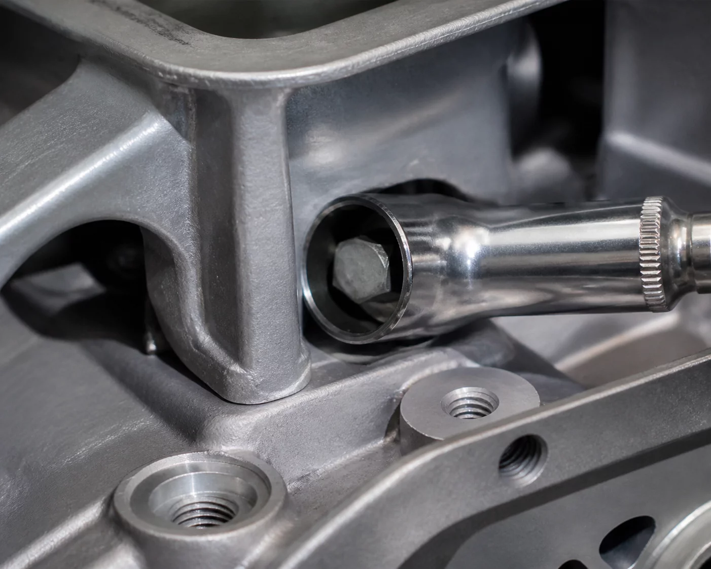
In solid modeling environments, designers frequently check for geometric interference by intersecting rigid solids. If the bolt model displays zero collision against the casting pocket, the interface is marked ready for production. However, assembly tooling requires an active, uninterrupted line-of-sight cylinder along the tightening axis. When an adjacent stiffening rib was relocated 8mm outward during weight optimization, it encroached directly on the socket wall diameter of a standard ratchet extension.

Intended Nominal Pathway

Straight +Z axial insertion for an M6 socket driver, requiring a minimum 16mm clearance diameter from the bolt center to any standing vertical wall.

Actual Assembly Conflict

A 15-degree drafted casting rib left only 7.2mm of radial space, causing the driver socket to bind against the wall before engaging the fastener head.

Dimensional & Tolerance Interplay

Fasteners behave not as isolated elements, but as parts of dynamic spatial paths. Standard CAD assemblies do not automatically generate bounding cylinders representing tool chucks, extension bars, or operator fingers. Without modeling these reserved clearance volumes as negative spatial bodies during initial envelope planning, assembly snags remain hidden until physical hardware hits the bench.

Technical Verification Modules

Select a perspective below to inspect the interface solution details.

Datum & Locating Surface Controls

The structural flange utilizes primary Datum A on the lower face, fixing 3 degrees of spatial freedom. However, locating bosses constrained the assembly in such a way that no angular tilt was permitted to cheat the driver past the rib.

  • Primary locating constraint: Plane A (Flange Face)
  • Secondary pin locator: Feature B (M6 Clearance Bore)
  • Rotational orientation lock: Slot C (Anti-rotation Rib)

Frequently Examined Interface Issues