Interface Study 2026-08-01 Lead: Diana White

The Interface Worked in CAD but Not in Assembly

A diagnostic investigation into why an enclosure subassembly paired effortlessly on the digital canvas but seized instantly when physical hardware met production tolerances.

Prime Mechanical Inquiry

“What geometric, fastener, or datum condition must remain true for this joint to assemble without conflict?”

Interface Parameters

V-2026.8
Datum Type:
3-Plane Planar Datum
Tool Clearance:
4.2 mm Envelope
Assembly Vector:
Linear Z with ±1.5° Swivel
Interface Status:
Analyzed & Resolved
Jump to Full Breakdown
Mechanical Interface Breakdown Diagram
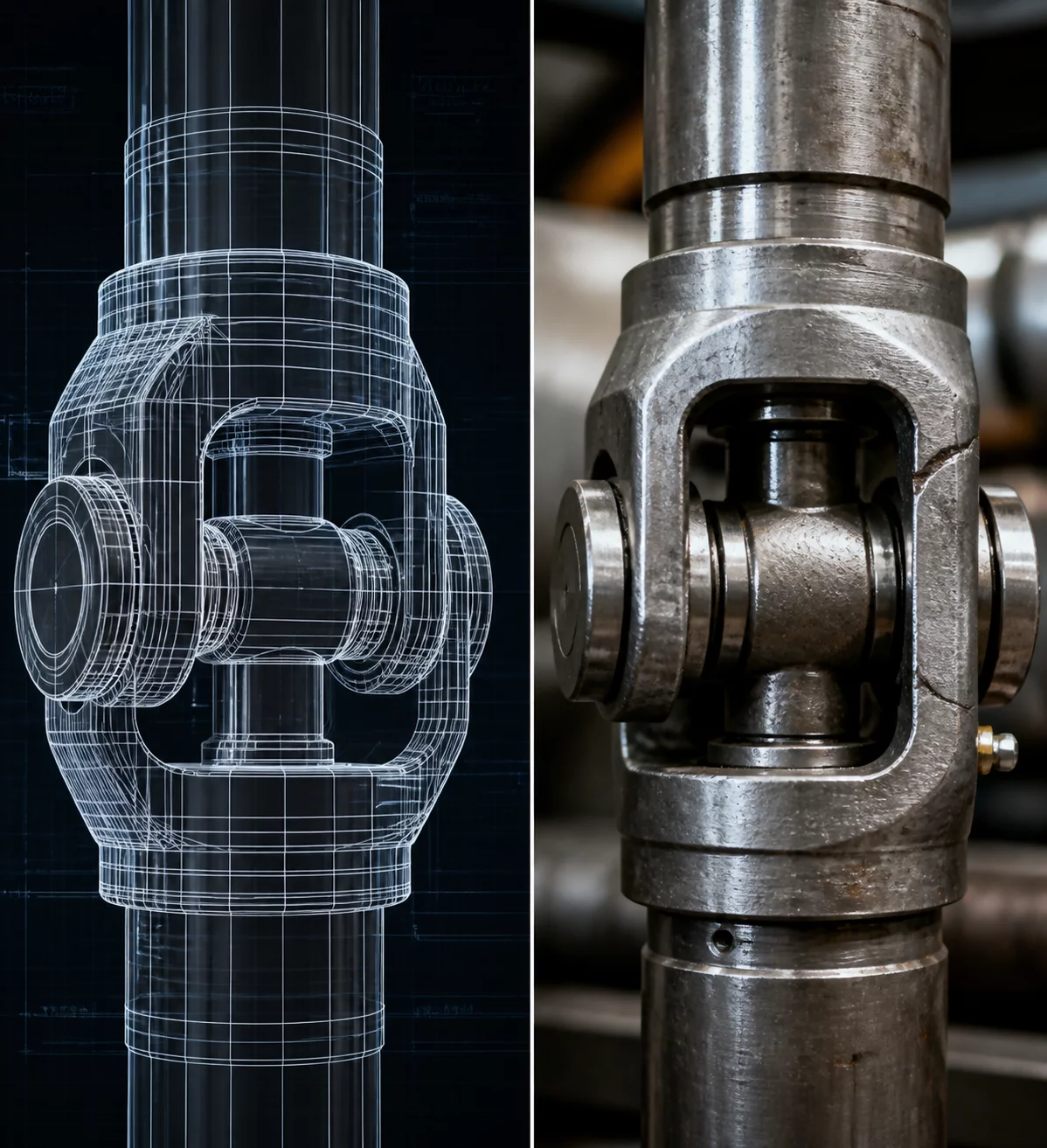
Primary Interface Section CAD View
Cross-section alignment model Interface Reason Repository #MB-1304

Root Interface Condition Analysis

In digital 3D modeling environments, solid bodies exist in a frictionless zero-tolerance state where planar faces glide together without physical resistance. During physical prototype assembly, stacked manufacturing variations on sheet metal bends and machined bosses produced an interference of 0.35 mm across the secondary mating interface, causing instant binding.

Intended Nominal Pathway

CAD geometry assumed perfectly orthogonal mating planes and concurrent fastener seating without deflection under clamp loads.

Actual Assembly Conflict

Physical parts exhibited slight angle drift and thermal powder-coat buildup, forcing technicians to force alignment with drift pins.

Dimensional & Tolerance Interplay

The failure stemmed from redundant dimensional constraints. By locating the mating bracket across two rigid planar faces simultaneously while maintaining tight pin-hole fits, the design overconstrained the horizontal axis. Eliminating the duplicate locating pad and converting one round dowel hole into a slotted relief restored immediate hand-assembly without binding.

Technical Verification Modules

Select a perspective below to inspect the interface solution details.

Datum & Locating Surface Controls

The primary datum plane establishes initial depth and pitch alignment, whereas secondary and tertiary locators restrict planar translation without inducing lateral overconstraint.

  • Primary locating constraint: Plane A (Machined Base Flange)
  • Secondary pin locator: Feature B (Diamond Dowel Pin #1)
  • Rotational orientation lock: Slot C (Relieved Slot Clearance)

Frequently Examined Interface Issues