Interface Study 2026-08-14 Lead: Michael Chang

Access for Assembly and Service

Planning spatial envelopes for driver clearance, manual hand access, and field maintenance during 3D CAD modeling.

Prime Mechanical Inquiry

“What geometric, fastener, or datum condition must remain true for this joint to assemble without conflict?”

Interface Parameters

V-2026.8
Datum Type:
Fastener Head Plane
Tool Clearance:
38.0 mm Radial
Assembly Vector:
Z+ Vertical Direct
Interface Status:
Validated Envelope
Jump to Full Breakdown
Access for Assembly and Service Demonstration
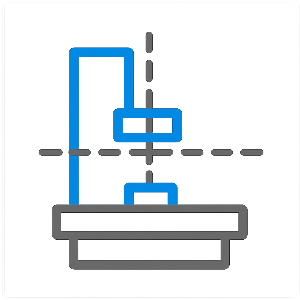
Primary Interface Section CAD View
Cross-section alignment model Interface Reason Repository #TC-03-ACC

Root Interface Condition Analysis

Physical assembly conflicts regularly emerge when digital models neglect tool swept volumes. Components that mate flawlessly in a static solid model can quickly turn into assembly bottlenecks if technicians cannot reach fastener heads with standard drivers. Access planning demands defining swept tool envelopes as permanent reference geometry right from initial concept sketches.

Intended Nominal Pathway

Direct coaxial driver entry with a minimum 40 mm axial clearance and unobstructed radial tool engagement throughout a 60-degree swing arc.

Actual Assembly Conflict

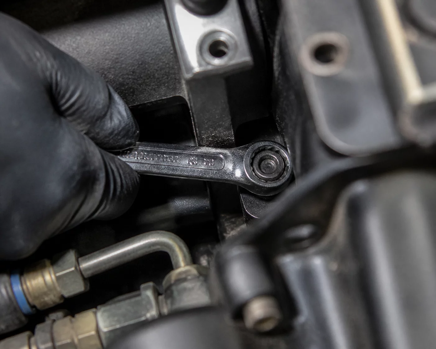
Overhanging structural ribs on neighboring brackets collide with driver sockets, forcing technicians into high-wear off-axis fastening methods.

Dimensional & Tolerance Interplay

Clearance bounds must account for the accumulation of machining tolerances across adjacent housings and mounting brackets. A minor angular deviation in a cast wall or a nominal sheet-metal bend offset can displace a fastener opening by several millimeters relative to its tool entry port. Modeling generous tool channels with positive lead-in chamfers protects assembly lines against unpredictable field fitting delays.

Technical Verification Modules

Select a perspective below to inspect the interface solution details.

Datum & Locating Surface Controls

Rigid locating features establish part alignment prior to screw thread engagement, preventing fasteners from carrying unintended shear loads during torque-down.

  • Primary locating constraint: Plane A-01 (Mating Face)
  • Secondary pin locator: Feature B-02 (Alignment Boss)
  • Rotational orientation lock: Slot C-03 (Guide Channel)

Frequently Examined Interface Issues