Interface Study 2026-08-10 Lead: Fiona Black

The New Bracket Blocked Service Access

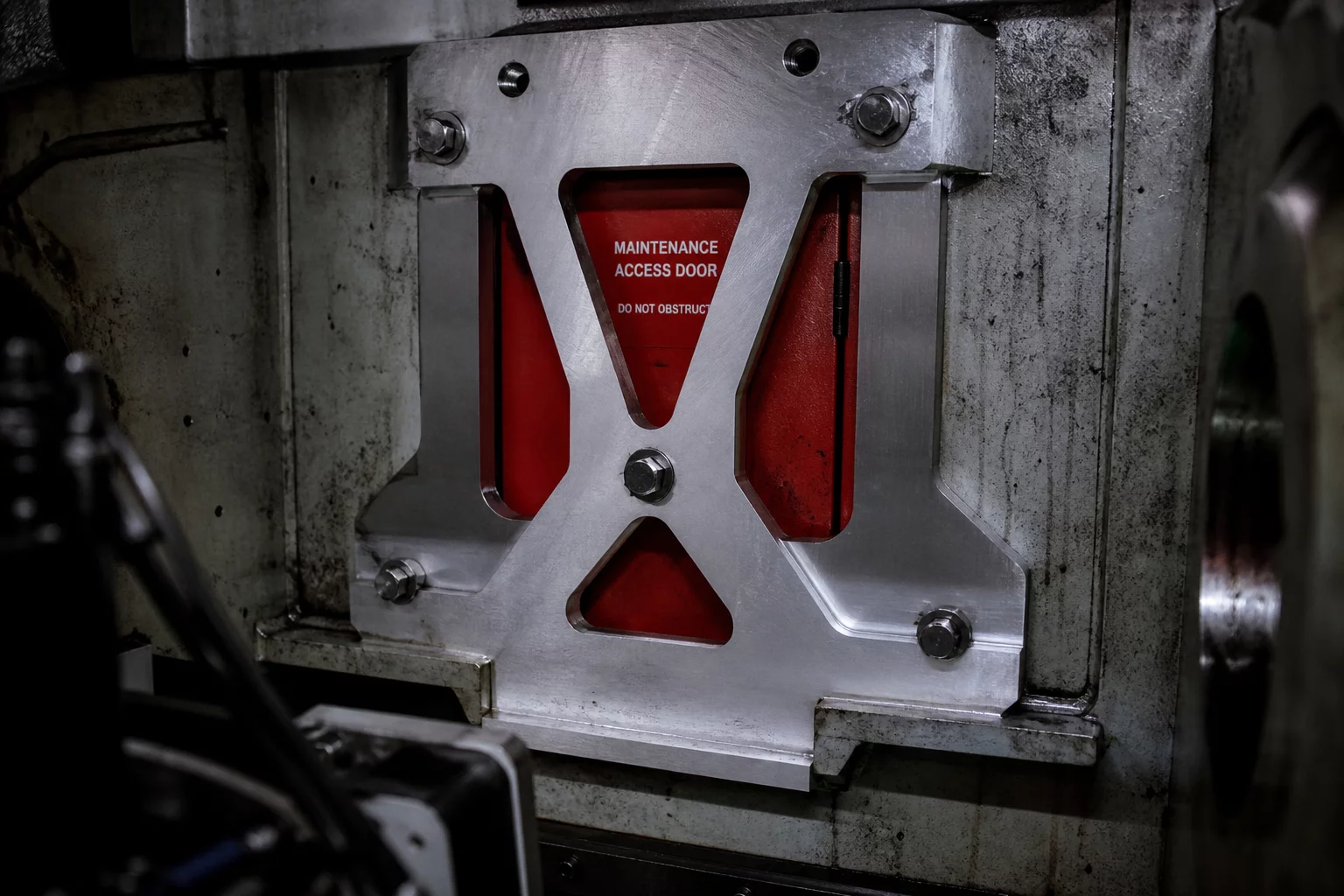
A structural reinforcement revision solved local modal vibration but unintentionally swept across the service access zone, blocking socket wrench travel and routine sensor servicing.

Prime Mechanical Inquiry

“What geometric, fastener, or datum condition must remain true for this joint to assemble without conflict?”

Interface Parameters

V-2026.8
Datum Type:
Dual Face Planar Joint
Tool Clearance:
14.2 mm (Required 48 mm)
Assembly Vector:
Uniaxial Normal +Z Axis
Interface Status:
Geometry Resolved
Jump to Full Breakdown
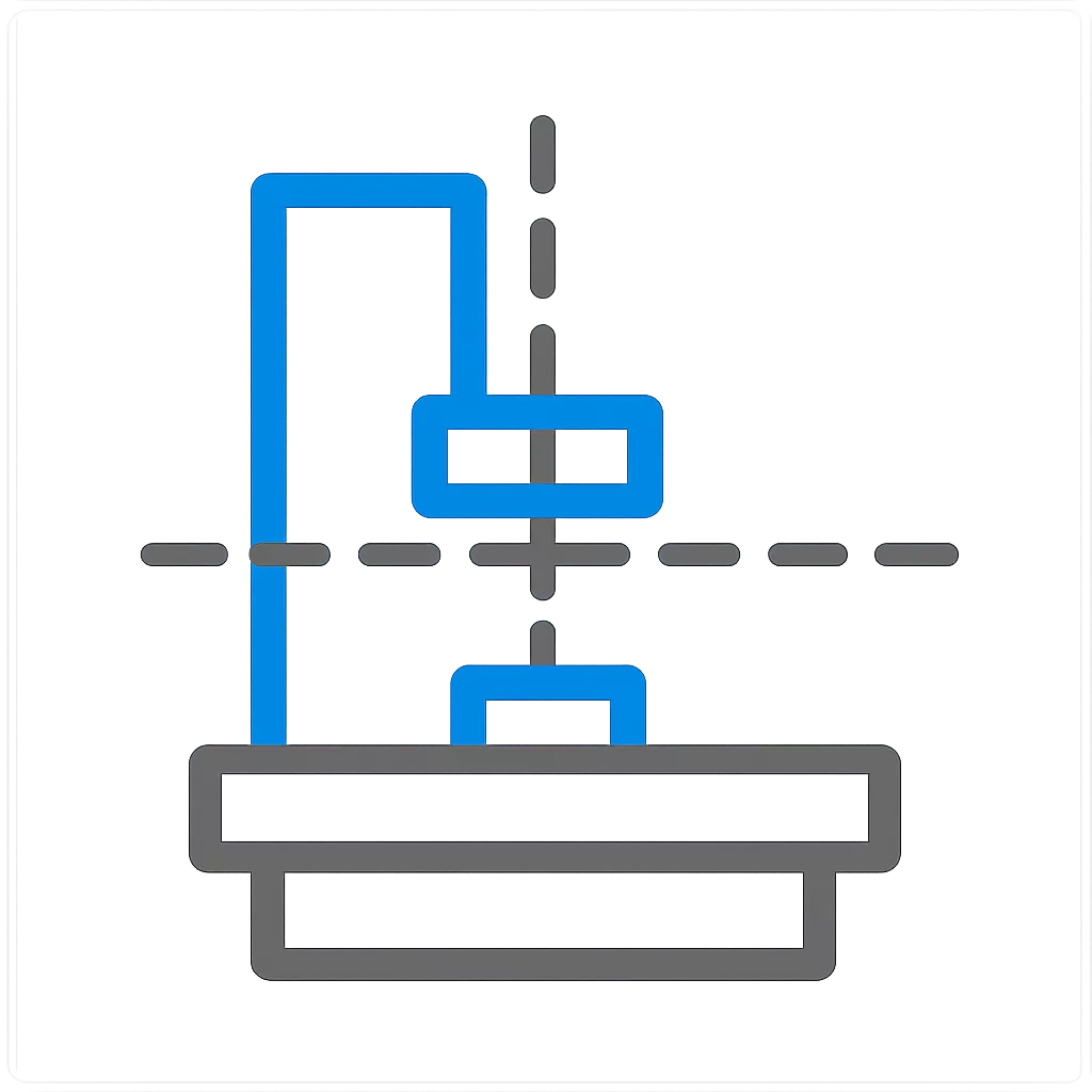
Mechanical Interface Breakdown Diagram
Primary Interface Section CAD View
Cross-section alignment model Interface Reason Repository #MB-824-SRV

Root Interface Condition Analysis

During mid-cycle testing, excessive vibration on the primary motor housing forced designers to reinforce the structural bracket with an enlarged gusset rib. The revised geometry passed finite element stress checks effortlessly, yet it swept directly across the neighboring access channel. When field technicians attempted the routine replacement of the lower fluid valve, standard ratchet heads collided against the newly added flange wall, requiring complete teardown of the structural frame just to loosen two fasteners.

Intended Nominal Pathway

Direct linear tool approach allowing a standard 1/4-inch hex drive socket to engage the service panel bolts within a dedicated 52 mm clear corridor.

Actual Assembly Conflict

The stiffener bracket rib protruded 38 mm into the tool clearance path, leaving only 14.2 mm of operational room and preventing any direct wrench alignment.

Dimensional & Tolerance Interplay

CAD clearance checks often evaluate only stationary nominal surfaces, missing the dynamic sweep of maintenance tooling and human hand articulation. In this mechanism, the nominal gap between the bracket rib and the valve screw head was barely 18 mm. Adding positive sheet-metal fabrication tolerances (+1.5 mm) and driver head diameter (28 mm), the clearance condition became mathematically impossible during physical maintenance tasks.

Technical Verification Modules

Select a perspective below to inspect the interface solution details.

Datum & Locating Surface Controls

The revised bracket references the primary chassis datum plane, while keeping secondary pin locations isolated from the maintenance access window to preserve independent serviceability.

  • Primary locating constraint: Plane [Datum A-Base]
  • Secondary pin locator: Feature [Pin Bore B2]
  • Rotational orientation lock: Slot [Radial Notch C1]

Frequently Examined Interface Issues