Root Interface Condition Analysis
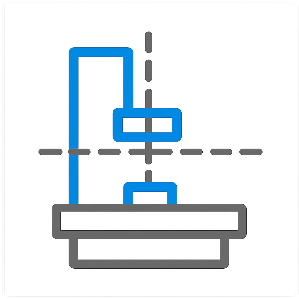
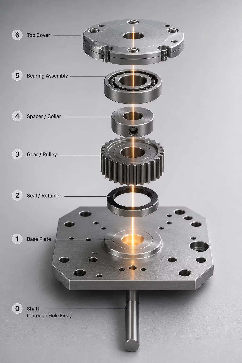
In complex mechanical housings, assembly steps frequently depend on a strict hierarchical order established by locating features. During the initial prototype phase of this structural gearbox mount, designers positioned a single 6 mm locating hole deep inside the lower chassis pocket. This hole was intended to pilot a precision dowel pin aligning the intermediate carrier. However, because the dowel had to seat before fastening the chassis rib, every other subcomponent—including the internal drive shaft, peripheral wiring loom, and side brackets—was forced into a single, non-negotiable sequence. Any minor rework required complete teardown of all upstream parts.
Nominal CAD planning assumed the central shaft and adjacent brackets could slip past the locating pin after insertion.
Physical assembly revealed zero line-of-sight and negative wrench swing radius once the pin was pressed, freezing subsequent fastener installation.
Dimensional & Tolerance Interplay
Dimensional stack-up compounding made the rigid sequence even more problematic. With positional tolerances of ±0.05 mm across three mating interfaces, thermal expansion during high-load testing introduced micro-binding along the fixed pin axis. By decoupling the alignment datum from the structural bolt hole and switching to an externally accessible slotted locating boss, the entire assembly sequence was reduced from seven sequential dependencies down to two parallel sub-assemblies.