Interface Study 2026-08-05 Lead: Evan Green

A Cosmetic Surface Became a Functional Datum

When industrial styling surfaces dictate internal mounting positions, tolerance stacks and tooling draft angles cascade into severe dimensional misalignment.

Prime Mechanical Inquiry

“What geometric, fastener, or datum condition must remain true for this joint to assemble without conflict?”

Interface Parameters

V-2026.8
Datum Type:
Form Profile / Outer Class-A
Tool Clearance:
1.8 mm (Marginal)
Assembly Vector:
Z-Axis Constrained Blind Mate
Interface Status:
Overconstrained (Resolved)
Jump to Full Breakdown
Mechanical Interface Breakdown Diagram
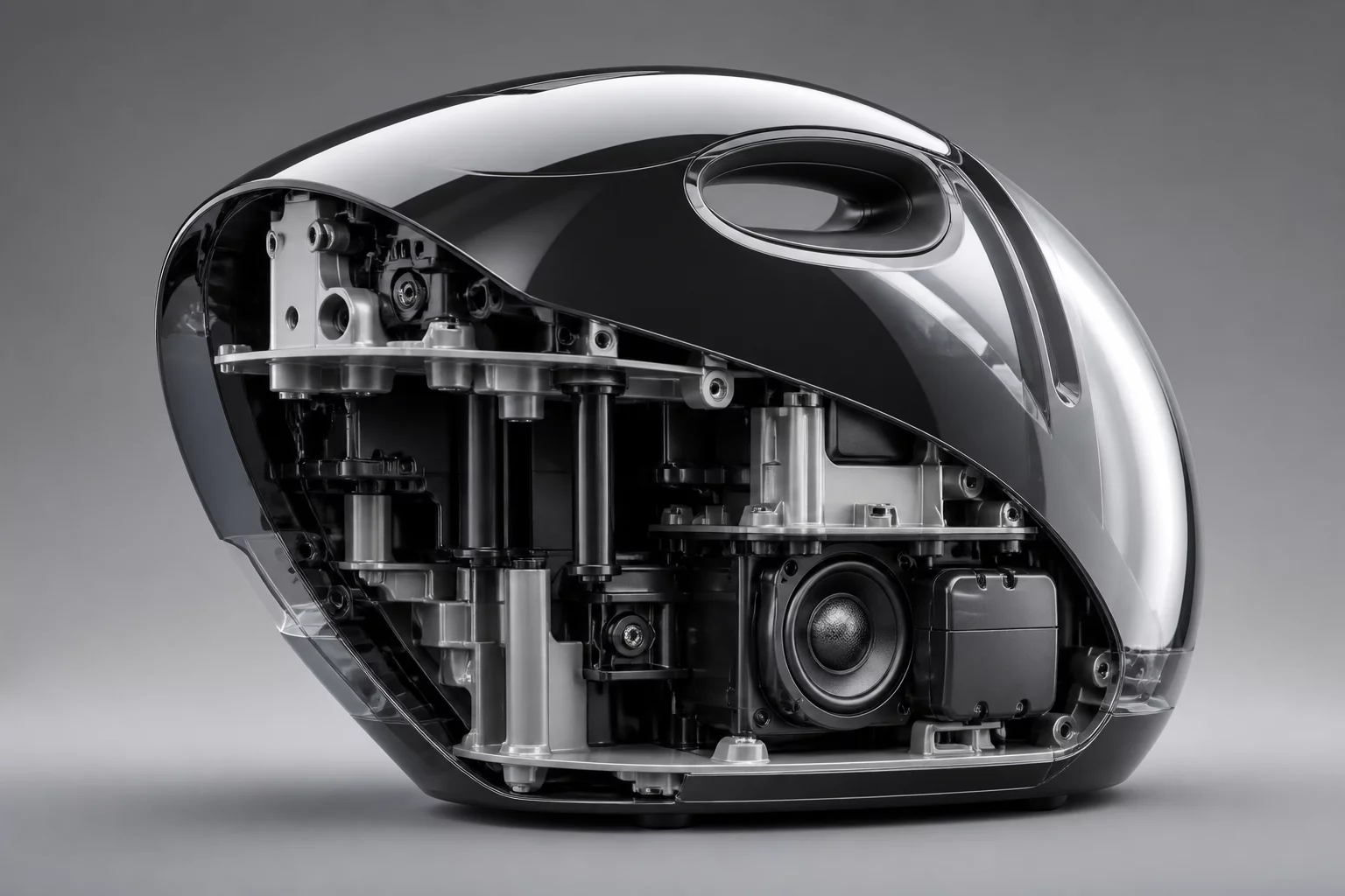
Primary Interface Section CAD View
Cross-section alignment model Interface Reason Repository #MB-4402

Root Interface Condition Analysis

In consumer electronics and industrial product enclosures, industrial design teams frequently refine outer aesthetic contours late in the design cycle. In this case study, a high-gloss curved exterior housing unexpectedly served as the primary reference locating datum for a precision internal optical carriage bracket. Because injection molding shrinkage rates, rib sinkage, and thermal expansion vary significantly across textured organic surfaces, referencing critical internal optics from an aesthetic outer shell introduced unpredictable 0.65 mm spatial shifts during final fastener torque down.

Intended Nominal Pathway

The internal chassis plate mounts directly to rigid metal boss features referenced from the primary machined aluminum baseplate datum structure.

Actual Assembly Conflict

Optical carrier seated directly against the inside wall of the cosmetic outer skin, transferring enclosure warpage and draft variation directly into the optical line.

Dimensional & Tolerance Interplay

Mechanical datum definition must separate aesthetic envelopes from functional load and alignment paths. When an external surface acts as a datum feature, normal draft angles (typically 1.5° to 3°) induce uncontrolled planar tilt on mating fastener standoffs. As assembly operators tightened the internal bracket mounting screws, the drafted cosmetic surface forced the bracket to pitch by 1.2°, exceeding the angular tolerance envelope and pinching neighboring wire harness channels.

Technical Verification Modules

Select a perspective below to inspect the interface solution details.

Datum & Locating Surface Controls

Isolating functional datums requires decoupling the exterior skin from internal kinematic mounts. The solution converted the outer cover into a floating secondary cosmetic shell with slotted slip-fit bosses, transferring all positional constraints back to a planar datum rib on the rigid die-cast skeleton.

  • Primary locating constraint: Plane Primary Cast Skeleton Datum [A]
  • Secondary pin locator: Feature Precision Cylindrical Dowel Boss [B]
  • Rotational orientation lock: Slot Elongated Clearance Anti-Rotation Slot [C]

Frequently Examined Interface Issues