
Interface Study 2026-08-19 Lead: Linda Taylor

Revision Consequences in Mechanical Design

Modifying a single mating face or fastener clearance in an existing CAD assembly rarely stays isolated. This deep dive uncovers how downstream tolerances, tooling envelopes, and assembly sequence constraints cascade across interconnected mechanical parts.

Prime Mechanical Inquiry

“What geometric, fastener, or datum condition must remain true for this joint to assemble without conflict?”

Interface Parameters

V-2026.8
Datum Type:
Kinematic 3-2-1 Plane
Tool Clearance:
28.0 mm Radial Envelope
Assembly Vector:
+Z Axis Orthogonal
Interface Status:
Revision Cascade Checked
Jump to Full Breakdown
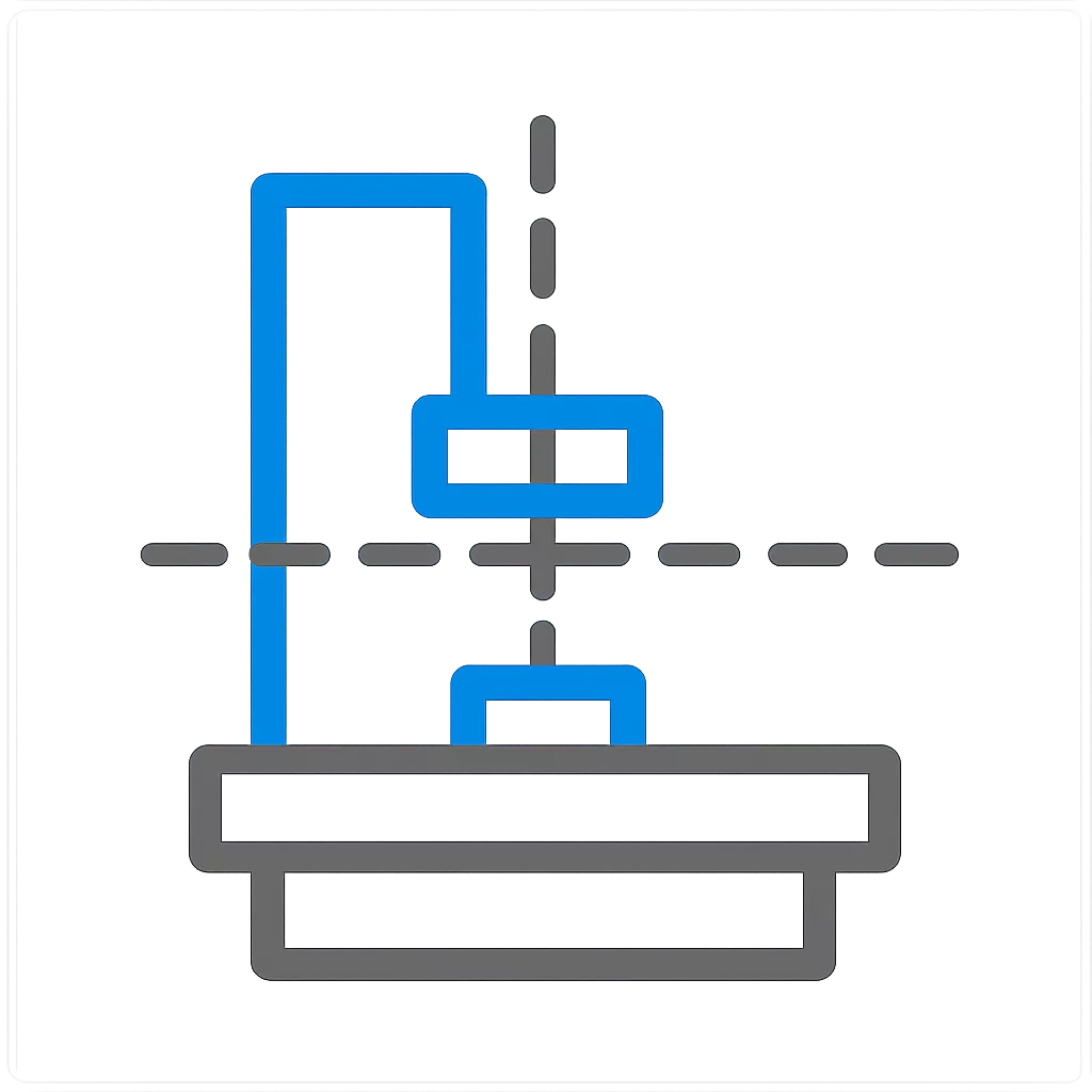
Mechanical Interface Breakdown Diagram
Primary Interface Section CAD View
Cross-section alignment model Interface Reason Repository #REV-8921

Root Interface Condition Analysis

When an engineering team adjusts a part boundary or shifts an internal fastener boss, the direct feature alteration is only the initial ripple. In complex assemblies, neighboring components depend on that exact reference face for positional alignment, clearance guarantees, and torque driver trajectories. Altering a single mounting flange thickness changes the bolt clamp length, shifts the thermal expansion equilibrium, and frequently forces an unintended re-sequencing of the entire sub-assembly build.

Intended Nominal Pathway

Flange revision preserves primary locating datum surfaces and maintains a consistent 30 mm straight-line clearance corridor for production power drivers without shifting adjacent harness brackets.

Actual Assembly Conflict

Thickening the rib moved the fastener centerline 3.5 mm inward, cutting the clearance envelope to 14 mm and making standard hex bits collide with the cast housing wall during stage two tightening.

Dimensional & Tolerance Interplay

A major risk during late-stage CAD revisions is tolerance stackup compounding across secondary locating pins. When a revision changes a primary surface finish or datum reference scheme without re-evaluating GD&T true position boundaries, individual tolerance zones shift from radial to angular errors. The resulting mismatch creates over-constraint conditions where fasteners bind against thread entrances before the mating faces achieve full face-to-face contact.

Technical Verification Modules

Select a perspective below to inspect the interface solution details.

Datum & Locating Surface Controls

Preserving the primary reference face prevents coordinate drift across mated modules. The revision must decouple aesthetic cover panels from structural datum chains to ensure repeatability.

  • Primary locating constraint: Plane Datum-A (Base Flange)
  • Secondary pin locator: Feature Pin-B1 (Ø6.00 +0.012/+0.004)
  • Rotational orientation lock: Slot Diamond Pin-C (6x10 mm)

Frequently Examined Interface Issues