Root Interface Condition Analysis
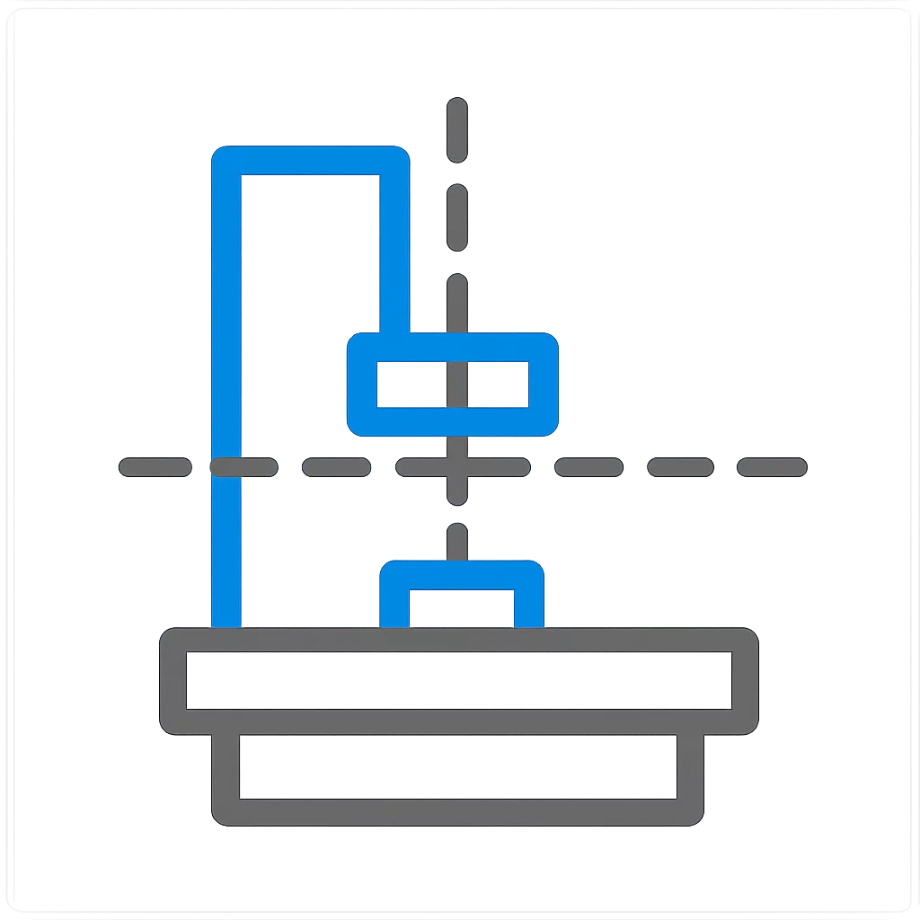
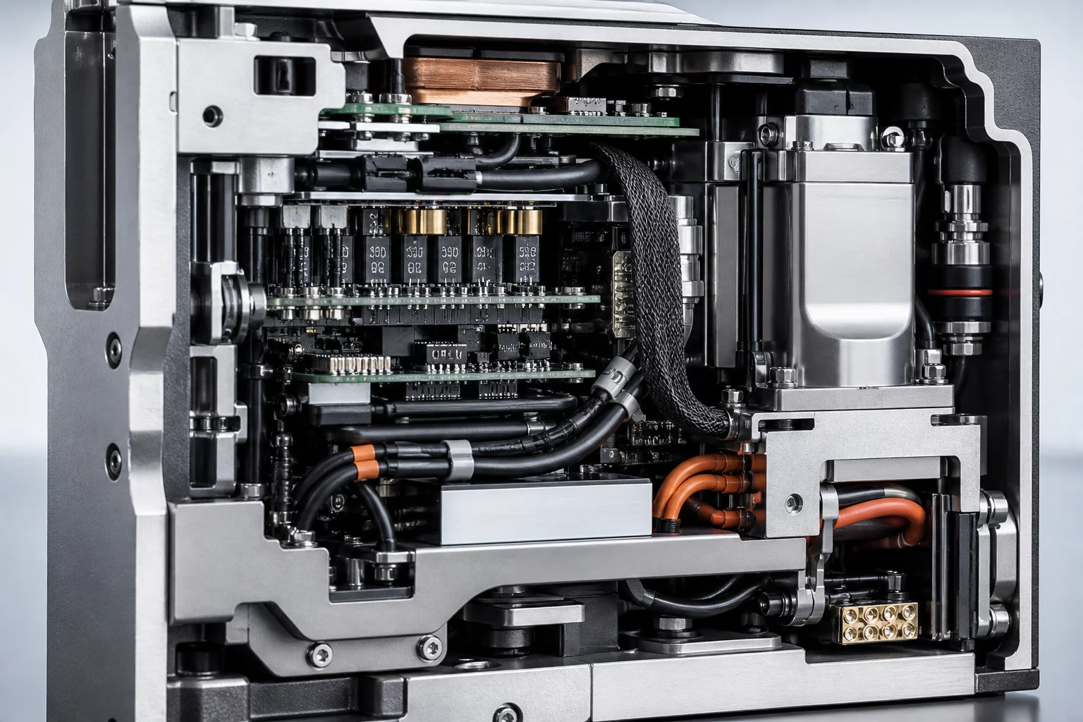
When packaging dense electromechanical assemblies, individual components rarely fail due to their own isolated dimensional tolerances. Instead, failures emerge at the boundaries where adjacent sub-assemblies fight for the same physical envelope. Modeling parts in isolation blinds design teams to the subtle volumetric intrusions that occur during dynamic movement, thermal expansion, or manual tool operations. Neighboring geometry constraints establish explicit spatial envelopes and keep-out volumes across mating subsystems, enforcing mutual clearance rules before detail drafting begins.
Adjacent module retains a 3.2 mm static envelope margin along the perimeter wall, permitting direct vertical insertion with standard hex bits.
Fastener tool sweep and wiring harness bend radii collide with the adjacent structural bracket during field maintenance maneuvers.
Dimensional & Tolerance Interplay
Managing neighboring geometry requires a rigorous balance between theoretical CAD nominal volumes and practical manufacturing variations. A static 1 mm gap between two housings might look generous on screen, but part warpage, surface coatings, fastener heads, and assembly tolerances will quickly erode this buffer down to direct interference. Defining shared interface datums and reserved volumetric boundaries ensures that any downstream revision on one part alerts the owner of neighboring parts instantly.