Interface Study 2026-08-21 Lead: Patricia Moore

Locating Features and Datums

A rigorous guide to kinematic positioning, GD&T datum reference frames, and avoiding over-constrained pin joints in multi-body assemblies.

Prime Mechanical Inquiry

“What geometric, fastener, or datum condition must remain true for this joint to assemble without conflict?”

Interface Parameters

V-2026.8
Datum Type:
3-2-1 Pin & Primary Plane
Tool Clearance:
24.5 mm Radial Envelope
Assembly Vector:
Z-Negative Insertion (0, 0, -1)
Interface Status:
Iso-static Verified
Jump to Full Breakdown
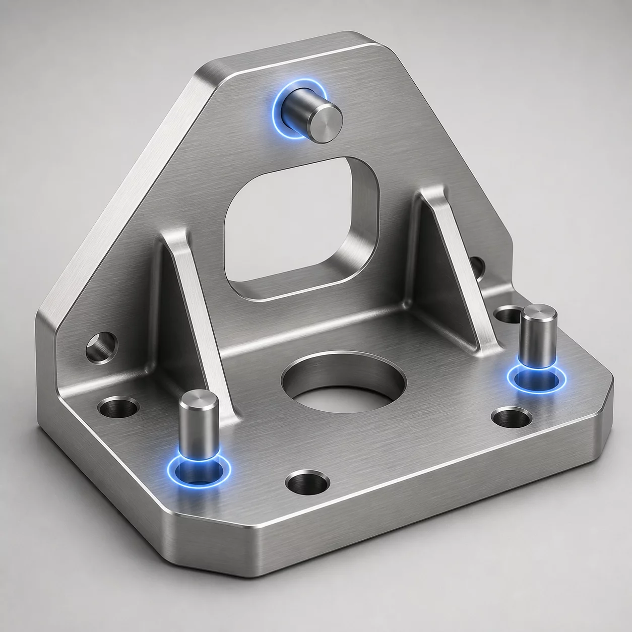
Locating Features and Datums mechanical setup diagram
Primary Interface Section CAD View
Cross-section alignment model Interface Reason Repository #DAT-804

Root Interface Condition Analysis

Locating features govern spatial repeatability and dictate exactly how parts nest before fasteners apply clamping load. When engineers confuse locating features with clamping fasteners, assemblies quickly suffer from positional drift, internal stress, and binding. A solid datum structure strictly isolates all six degrees of freedom without introducing redundant mechanical constraints.

Intended Nominal Pathway

Primary planar contact eliminates 3 degrees of freedom (Z-translation, X-rotation, Y-rotation), a precision round pin halts X and Y translations, and a secondary diamond pin arrests remaining Z-axis clocking rotation.

Actual Assembly Conflict

Using two round dowel pins with zero center-to-center pitch allowance locks distance tolerances, causing severe galling or total assembly refusal whenever ambient thermal shifts exceed 15 degrees Celsius.

Dimensional & Tolerance Interplay

Defining datums directly from functional faces rather than unmachined casting surfaces eliminates tolerance accumulation across mating parts. Precision locators should absorb minimal manufacturing variation, leaving clearance holes on fasteners to handle minor bolt misalignment without compromising the established mechanical datum structure.

Technical Verification Modules

Select a perspective below to inspect the interface solution details.

Datum & Locating Surface Controls

Primary datum surface must provide a coplanarity within 0.02 mm across three machined pads. Secondary locating hole controls XY origin, whereas the relief-cut slot controls orientation along the major axis.

  • Primary locating constraint: Plane [A] (3 coplanar milled pads)
  • Secondary pin locator: Feature [B] (Ø6.00 mm H7 round pin)
  • Rotational orientation lock: Slot [C] (Diamond relief locator)

Frequently Examined Interface Issues